What is the difference between NMOS and PMOS?
what is nmos?
NMOS the full name of English is N-Metal-Oxide-Semiconductor. It means N-type metal-oxide-semiconductor, and the transistor with this structure is called NMOS transistor. MOS transistor has P type MOS tube and N type MOS tube. The integrated circuit consisting of MOS transistors is called MOS integrated circuit. The circuit consisting of NMOS is NMOS integrated circuit. The circuit consisting of PMOS transistors is PMOS integrated circuit. The complementary MOS circuit consisting of NMOS and PMOS transistors is CMOS circuit.
The difference between nmos and PMOS is .
In actual projects, we basically use enhanced type.
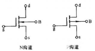
MOS pipes are divided into two types: N channel and P channel. We usually use NMOS because of its small on resistance and capacitance.
Easy to make. It can be seen from the MOS transistor schematic that there is a parasitic diode between the drain and the source. This is called body diode.
In driving inductive load (such as motor), this diode is very important. By the way, the body diode is only in a single MOS.
The existence of a tube is usually not internal to the IC chip.
1, conduction characteristic
The characteristics of NMOS, Vgs will turn on when the value is larger than a certain value, suitable for the case of source grounding (low-end drive), as long as the gate voltage reaches 4V or 10V. PMOS features, Vgs less than a certain value will be turned on, suitable for the source VCC when the situation (high-end driver). However, although PMOS can be easily used as a high-end driver, NMOS is usually used in high-end driver because of its high on-resistance, high price and few types of substitution.
Loss of 2.MOS switch tube
Whether NMOS or PMOS, there is a conduction resistance after conduction, so the current will consume energy on this resistance, which is called conduction loss. Selecting a MOS tube with small conduction resistance will reduce the conduction loss. The current low power MOS transistor has a resistance of about tens of milliohms and a few milliohms. MOS must not be completed instantaneously at the time of conduction and cut-off. The voltage at both ends of the MOS goes down and the current flows up. During this period, the loss of the MOS transistor is the product of voltage and current, which is called switching loss. Usually, the switch loss is much larger than the conduction loss, and the higher the switching frequency, the greater the loss. The large amount of voltage and current at the instant of conduction leads to great losses. By shortening the switching time, the loss of each turn-on can be reduced, and by reducing the switching frequency, the switching times per unit time can be reduced. These two methods can reduce switching losses.
3.MOS tube driven
Compared with bipolar transistors, it is generally believed that no current is needed for MOS transistors to turn on as long as the GS voltage is higher than a certain value. This is easy to do, but we still need speed. It can be seen in the structure of MOS transistor that parasitic capacitance exists between GS and GD, and the drive of MOS transistor is actually the charge and discharge of capacitance. Charging a capacitor requires a current, because the capacitor can be regarded as a short circuit at the moment of charging, so the instantaneous current will be larger. The first thing to pay attention to when choosing / designing MOS tube drives is to provide instantaneous short-circuit current.
Second, it should be noted that the gate voltage is larger than the source voltage when conducting NMOS, which is commonly used for high-end drive.
The source voltage and drain voltage (VCC) of the high-end drive MOS transistor are the same when it is turned on, so the gate voltage is higher than that of VCC.
Big 4V or 10V. If you want to get a voltage larger than VCC in the same system, you need a special boost circuit. very
Charge pumps are integrated into multi-motor drives. It should be noted that appropriate external capacitors should be selected to obtain sufficient short-circuit power.
Flow to drive MOS tube.